About
Design Overview
I designed this device with the intention of testing my mechatronics capabilities. Upon entering the University of Waterloo for mechatronics, I was always told "by the end of this degree, you will have the skills required to build a robot". This sounded really cool to me, and unlike many of my classmates I had no clue where to start with something like this. This project, designed in my third year, was a culmination of many of the skills I have been gradually developing.
Strategy
Research
This project is multidisciplinary, and thus requires technical skills from all sides of mechatronics - mechanical, electrical, and firmware. While I have a vast background in mechanical design, I am not as versed on the electrical/firmware sides. Thus, I would need to research some background to better understand and define the problems.
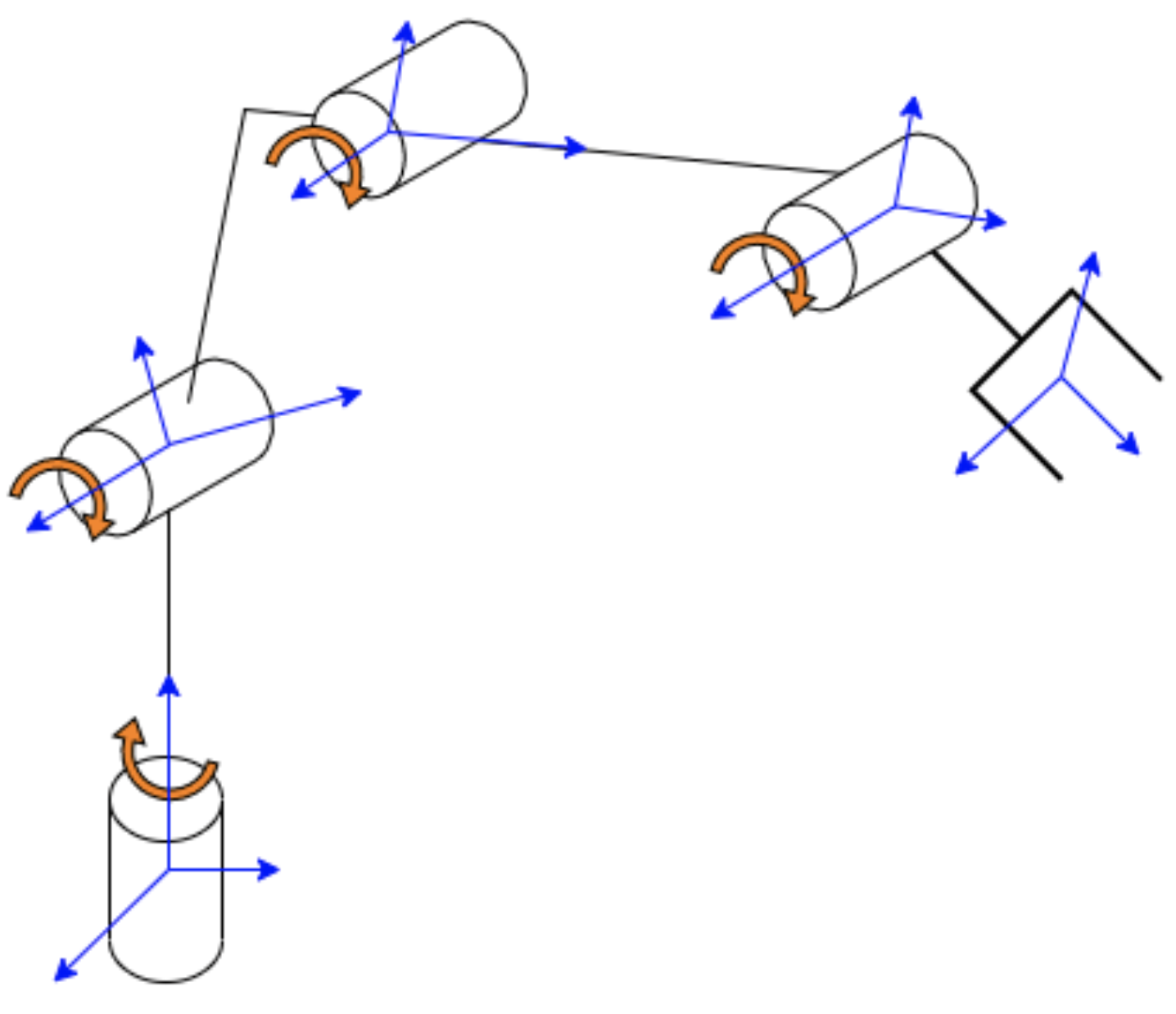
4DOF Robotic Arm Joint FBD
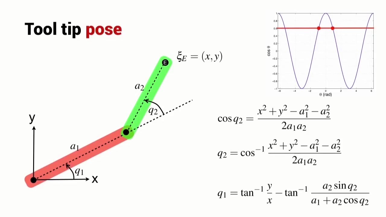
Inverse Kinematics of 2-Segment Arm
The project began with an investigation into the kinematics of 4-degree-of-freedom (DOF) robotic arms, with a focus on low-cost, easily manufacturable designs suitable for 3D printing. Research included material strength and joint stability, specifically for 3D-printed components. Servo motors were identified as a viable option for movement due to their simplicity, cost-efficiency, and ease of integration into lightweight, small-scale robotic systems.
Development
Conceptual Design
The conceptual design featured a 4-DOF robotic arm, optimized for 3D printing with minimal assembly. Servo motors were chosen to actuate the rotary joints, providing sufficient torque and position control for light pick-and-place tasks. The arm's structure utilized reinforced 3D-printed segments, allowing for customizable lengths and shapes while reducing the need for external fasteners. The overall goal was to design a functional and compact system that could be rapidly prototyped and iterated.
Development
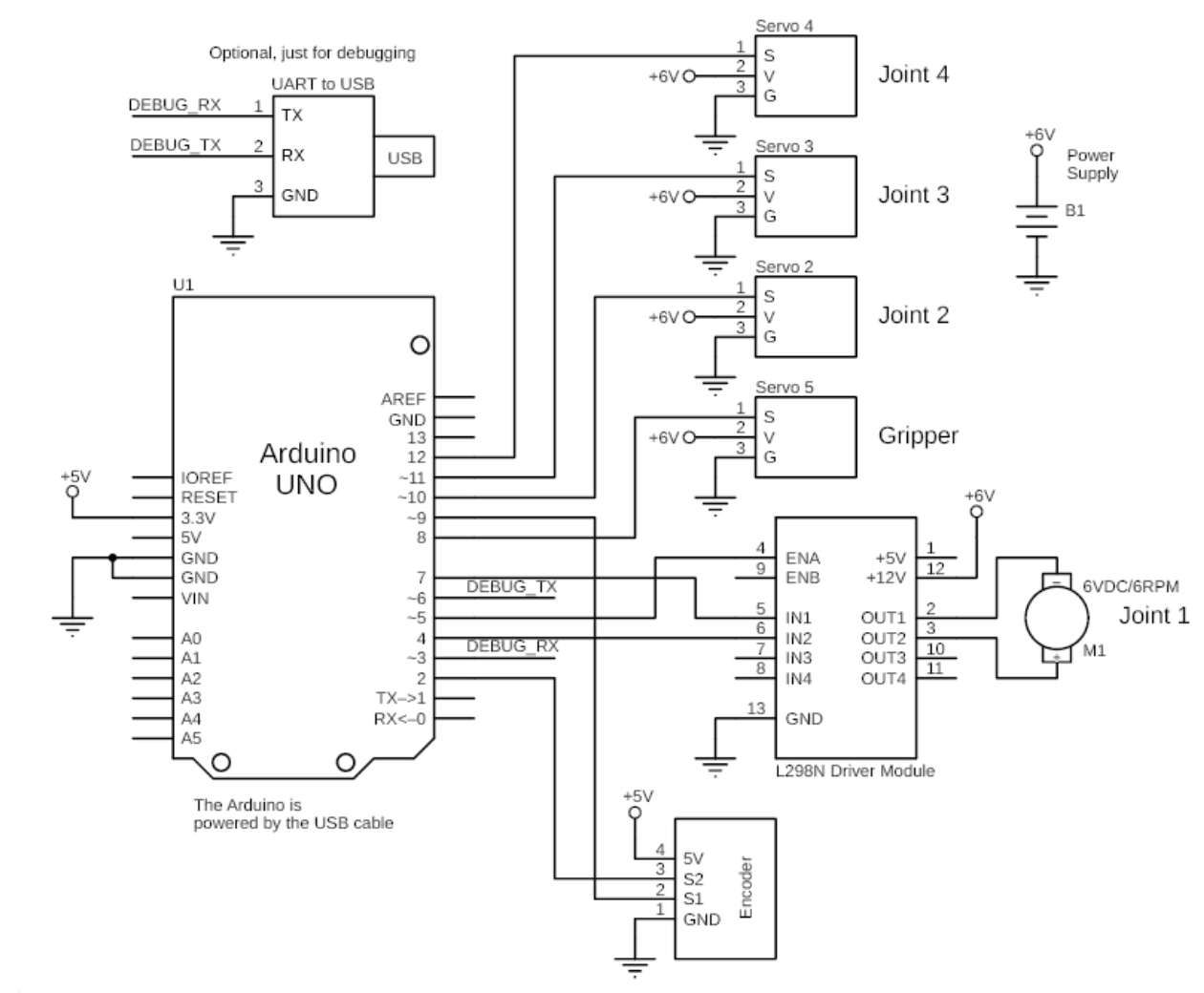
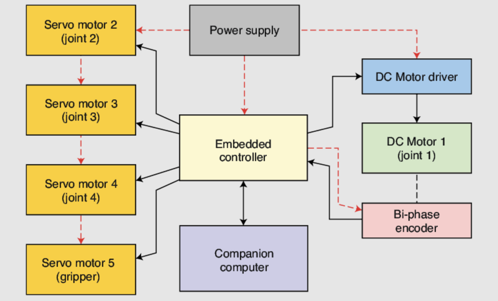
Control Architecture
The control system was built around a microcontroller with Pulse Width Modulation (PWM) to control the servo motors. The system used forward and inverse kinematics algorithms to calculate the required servo angles for precise end-effector positioning. Additionally, the control loop integrated position feedback from the servos to ensure smooth and accurate motion, with real-time adjustments for fine-tuning the arm’s movements.
Assembled Prototype
Motor Testbench
Development
Detailed Design & Analysis
The arm was fully modeled in CAD software, and finite element analysis (FEA) was performed to assess the load-bearing capabilities of the 3D-printed parts, particularly at the joints. The design incorporated stress-relief features such as fillets and reinforced walls to enhance durability. Torque requirements for each servo motor were calculated based on arm length and payload, ensuring that the selected servos provided adequate force without excessive power consumption.
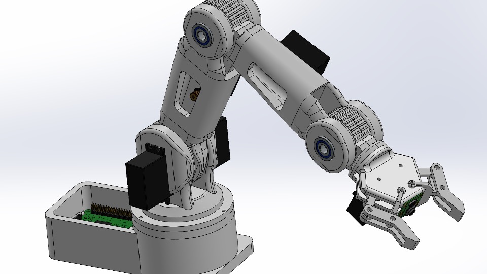
Final Design CAD
Manufacturing
Results
This project will be completed during Winter 2025 as part of course on Kinematics/Dynamics of Robotic Arms.