About
Design Overview
The goal was to create a low-cost quadcopter in an attractive form factor. This project is something that I have been slowly working on for 6 months, and is in continuous development. Long term, I am aiming to develop an autonomous drone with video streaming capabilities.
Prototype 1
Current Design
Step 1
Ideation
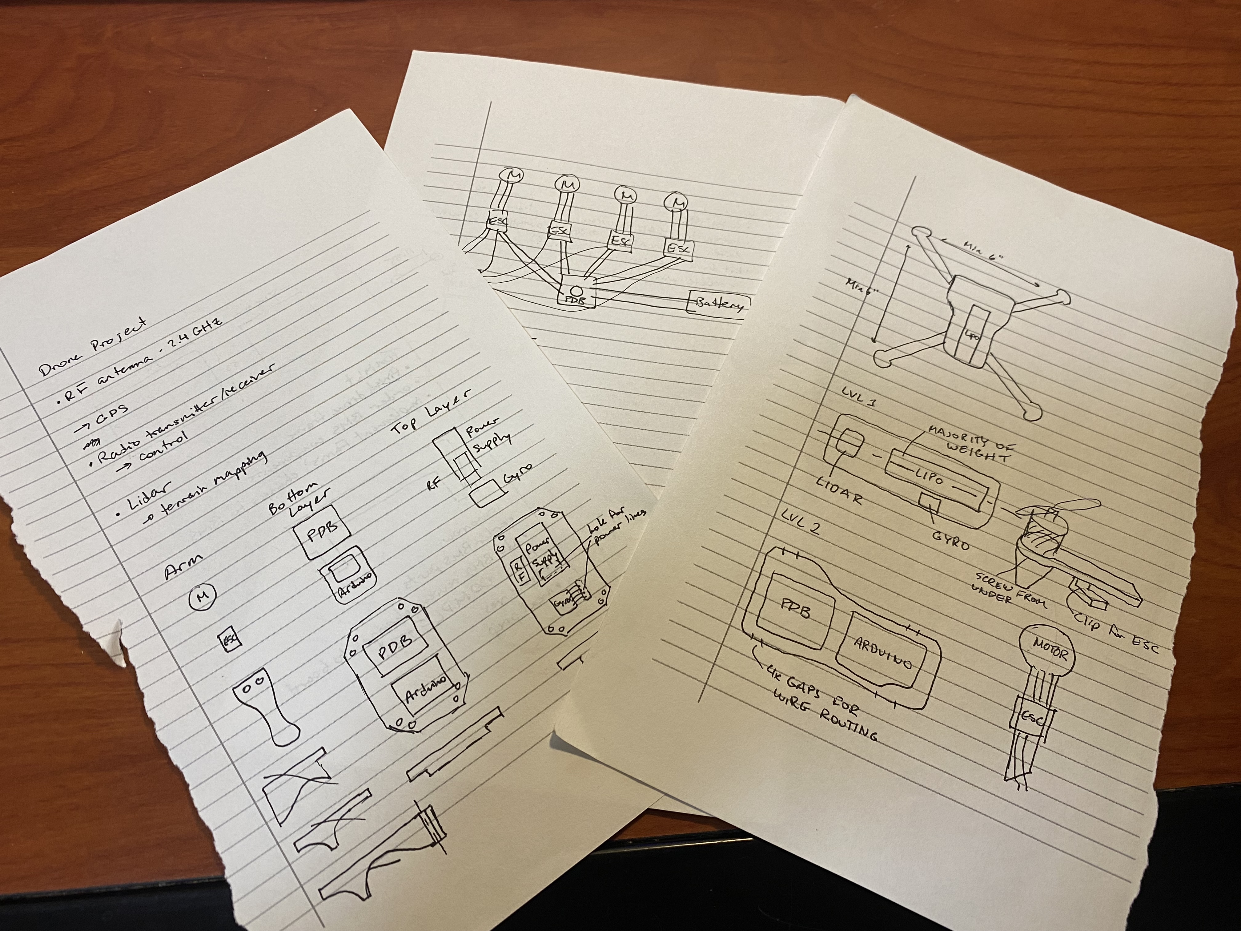
Keeping the goal in mind, I began searching for current quadcopter designs. I learned about different ways product designers enclose the components to minimize size and weight, and began creating concept sketches.
Step 2
Analysis & Electrical Architecture
It was then time to define performance objectives and source components. I knew I wanted to ensure adequate thrust-to-weight to allow for the addition of a camera in the future.
Components
Motors: 2300KV
ESCs: 30A, 2-4S LIPO, BEC: 5V3A
Battery: 2200mAh, 35C, 3S 11.1V
Flight Controller: Arduino Uno, 5V
Propellers: L:182mm W:23mm
I wanted to use an Arduino for the initial flight controller to keep costs low.
Calculations
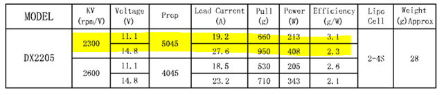
The table to the right gives the specifications of the motor-propeller combination being used for the design. From this, I was able to calculate the current draw by the motors and compare to the battery's current supply.
Battery: 2200mAh x 35C = 77000mA = 77A (supply)
Motors: 19.2A x 4 = 76.8A (draw)
Each motor = 11.1V -> 660g thrust
660g x 4 = 2640g total thrust
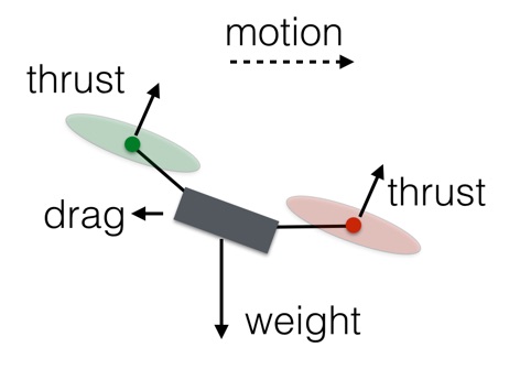
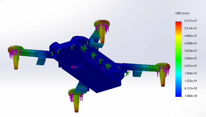
Structural analysis on the drone using thrust and weight gives the displacement shown to the right.
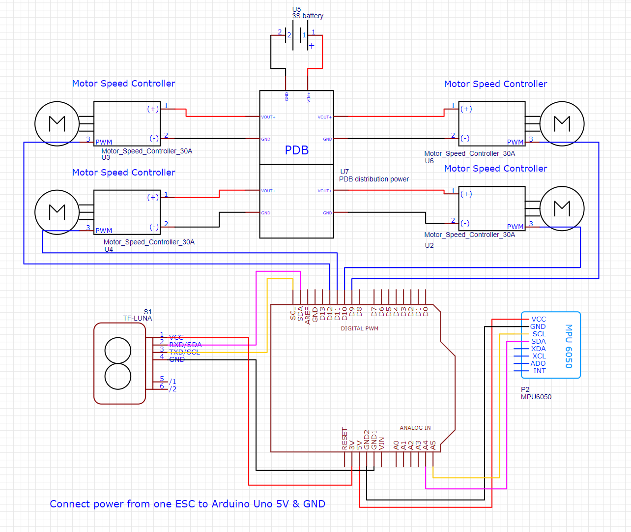
The arduino sends a signal to each motor using sensor readings from an IMU and a LiDAR sensor. A basic wiring diagram is included to the right.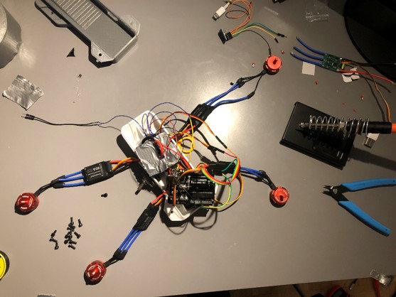
Step 3
Prototype 1
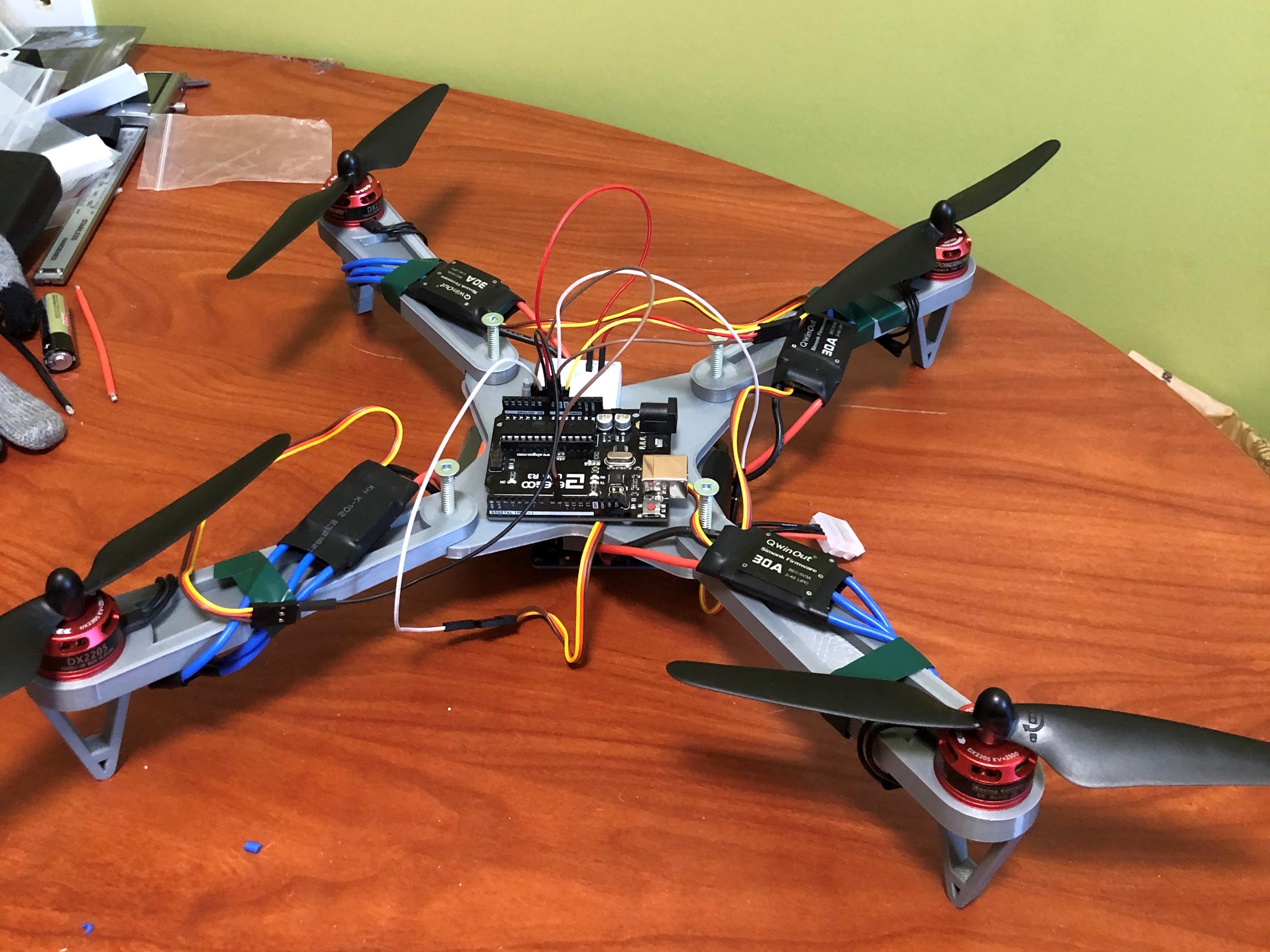
The first prototype was created to test the electronics. At this stage, motor performance testing was performed and the connections were verified.
Troubleshooting
The first prototype was designed for simplicity - a flat plate with attachments for the motors. This would allow me to get a feel for
the space required for the electronics and spacing of the propellers. After running the motors, it was clear that
there was an issue - one of the motors would not run. There was an audible beep as if it was powered, but when it was signalled
it did not respond. Using a multimeter I tested the voltage to the ESC, current from the Arduino, and current to the motor.
From this, it was clear that one of the ESCs was broken.
I removed the cover from the ESC and checked the board for damage,
but found nothing. The connections between components on the board seemed to check out however the motor would still not run. I figured there was
an issue with the ESC on-board firmware and thus I requested a replacement.
Assembled Prototype
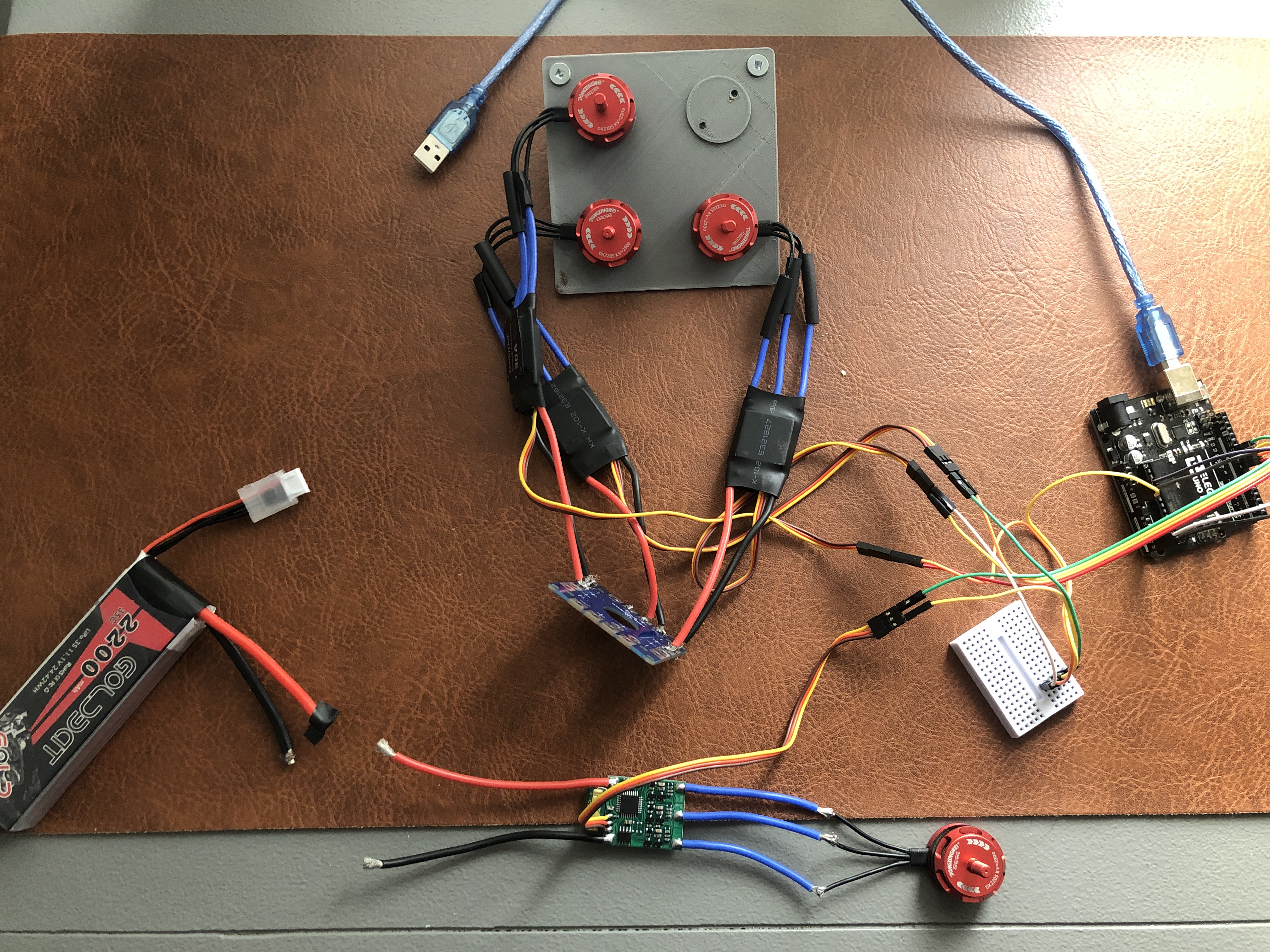
Motor Testbench
Step 4
Final Design
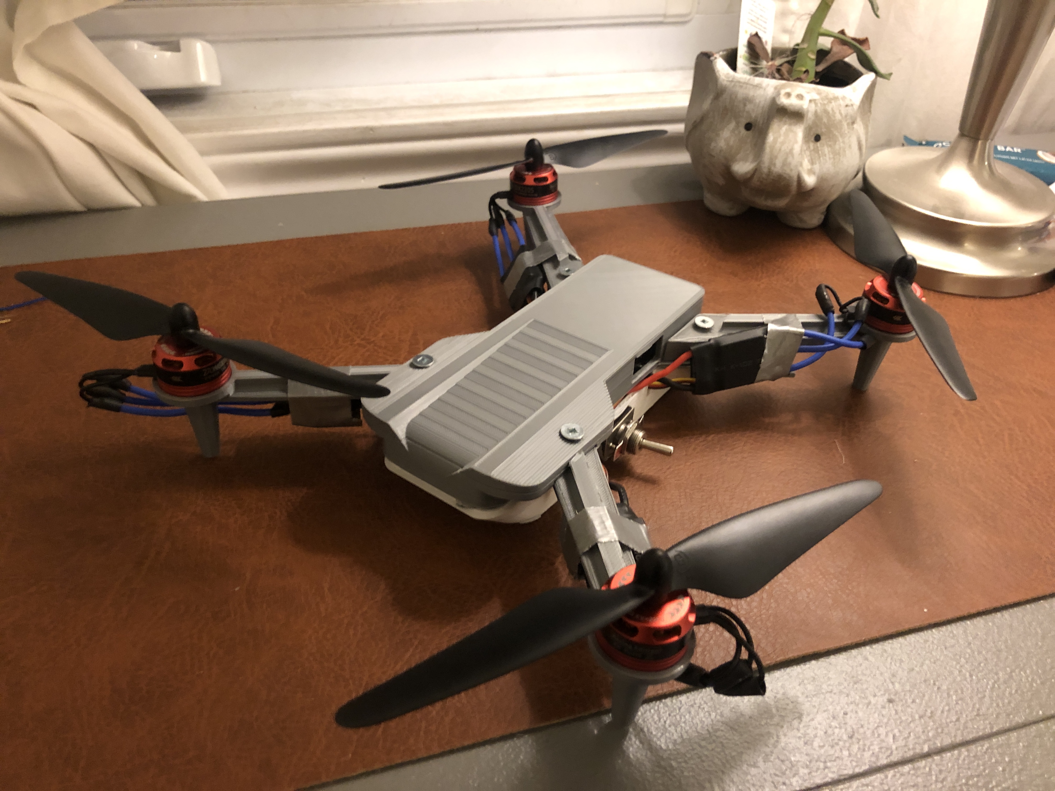
The final design was then created and 3D-printed.
Assembly
The final design was then created in Solidworks, with an aim to be easy to 3D print and assemble. The enclosure
was entirely 3D printed and uses screws and nuts that I had from a previous project for attaching the top and
bottom together.
In CAD, all of the internal components fit compactly within the body, however during assembly it was clear I
overlooked on crucial part - the wires themselves. Dupont wires commonly used for arduino projects stick up
very high from the board, and end up taking a lot of space. This meant I had to shift the battery off center
to fit everything within the build. While the final prototype looked good from the outside, the center of gravity
was shifted. It is later revealed through testing that this would not allow the drone to take off.
Testing
I ran the test several times, adjusting the internal layout of components between tests. The motors were set to gradually increase in rpm, and slow down once the LiDAR detected that it was off the ground. Since the weight was not centered, the motors were not able to adjust the tilt of the quadcopter based on the gyroscope readings, and thus the quadcopter tipped over.
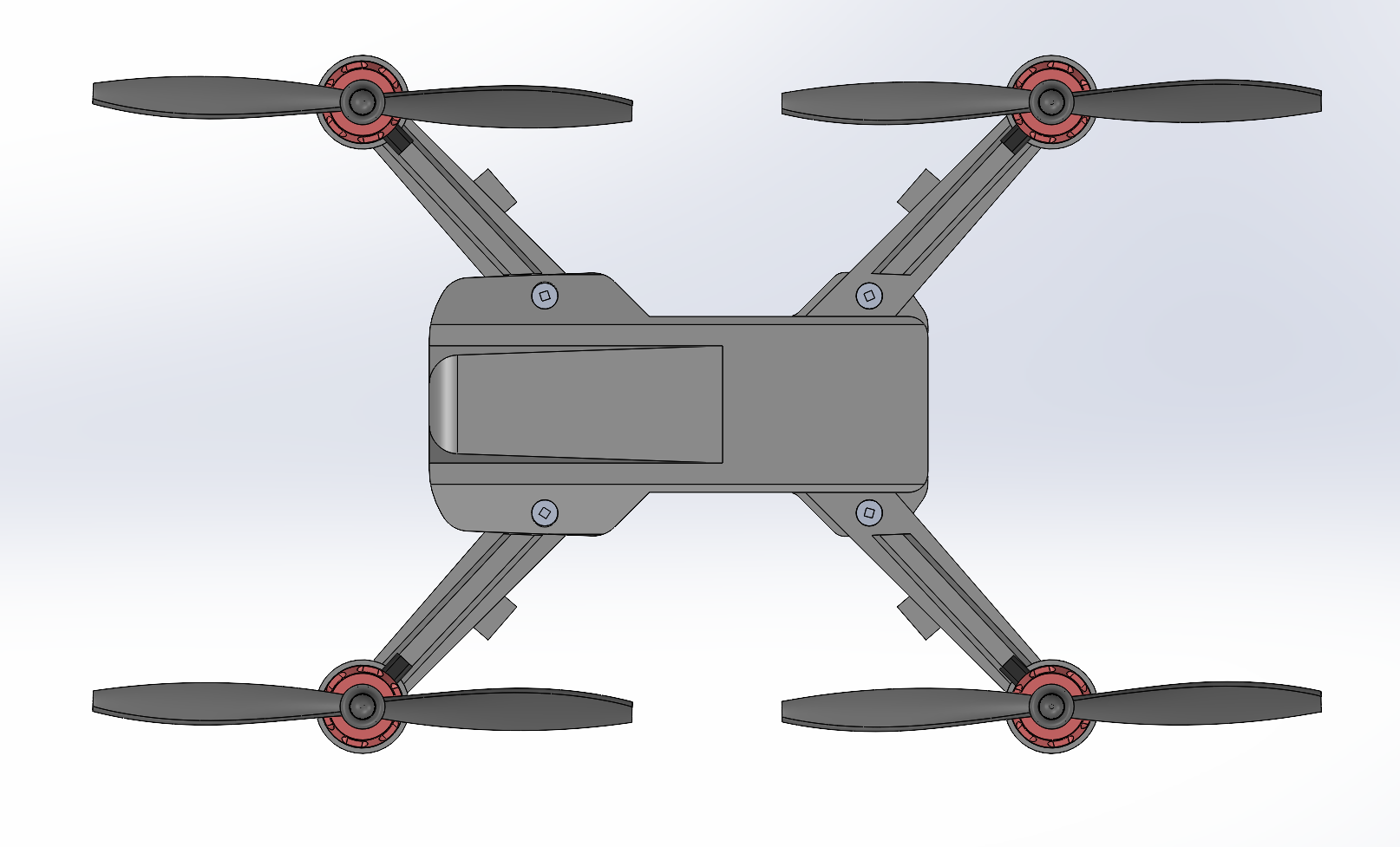
Final Design CAD
Final Assembly
Future Improvements
I am currently working on redesigning the enclosure to have a larger capacity and defined mounting for the internal components. I will ensure that the CG is properly centered in CAD prior to assembly and run more tests of the prototype vehicle.